


Program 07 · Educational preview
AI Accelerators, Computer Architecture & Semiconductor Systems Engineering
Understand how hardware carries out AI computation.
Engineers interested in architecture and hardware constraints.
Current curriculum and admission prerequisites are not published in the verified program source. Confirm them with the team.

Free educational reading
Explore this program through articles.
0 published articles · Reading times are calculated from the content.
Coming soon. Explore the teaching examples and exercises below while full articles are prepared.
Browse and filter articles →Understand the work
One example, step by step.
- Express a matrix operation
- Map work to compute units
- Move operands through memory
- Execute and store the result
Inspect the parts and their roles.
Compute units execute mapped arithmetic. They depend on operands arriving from the stated memory hierarchy. Inspect operation count and achieved execution behavior; a Roofline ceiling is not achieved throughput.
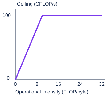
Which ceiling limits this hypothetical workload?
Calculated Roofline ceiling: min(peak compute, bandwidth × operational intensity). Authored device assumptions: 100 GFLOP/s compute and 10 GB/s memory bandwidth. Operational intensity counts FLOPs per byte transferred from the specified external memory. No measured performance.
Real performance can be below either ceiling. Cache reuse, precision, access pattern and synchronization change the model inputs. FLOP means floating-point operation.
Violet · compute array · Teal · memory · Amber · operands / result
A = [[1, 2], [3, 4]] and B = [[1, 0], [0, 1]] move from external memory into local memory.
How it works
Conceptual cutaway, not a commercial chip layout. This authored matrix example illustrates data movement and arithmetic.
Article draft · Awaiting editorial publication
What Happens Inside an AI Accelerator.
A matrix operation describes a result, but hardware must arrange computation and move the operands needed to produce it. Studying an accelerator means following both paths. A fast compute array can still wait for data.
Follow one operation from software to hardware
Consider multiplying two small matrices. Software represents the operation, a compiler or runtime organizes work, memory supplies operands, compute units execute arithmetic and the result is stored. The particular mapping depends on the implementation and device.
The illustration is an exploded conceptual assembly: compute array, memory hierarchy, interconnect and host interface. Its layout is not the floorplan of a commercial chip. Semiconductor engineering involves deeper device, fabrication and physical-design constraints that this teaching cutaway does not reproduce.
The editable mechanism below multiplies a two-by-two matrix by an identity matrix. An identity multiplication returns the original matrix; it is a transparent example for tracing operands, not evidence of accelerator performance.
The data source determines the intensity
Operational intensity counts floating-point operations per byte transferred from a specified memory level. Reusing an operand before fetching it again can change that count. You must state which transfers you count; “memory bandwidth” without a boundary is ambiguous.
The Roofline model relates intensity to compute and bandwidth ceilings. Our calculated graph assumes a hypothetical 100 GFLOP/s peak and 10 GB/s external-memory bandwidth. The ceiling is the smaller of 100 and ten times intensity.
At four FLOP per byte, the bandwidth ceiling is forty GFLOP/s. At ten, the two ceilings meet. Above that point the compute ceiling is lower. These are bounds under authored assumptions, not achieved measurements or specifications of a real device. Actual execution can be lower because of access patterns, synchronization and other effects.
Exercise: calculate before benchmarking
Run the supplied CPU-only architecture script. It performs a small matrix multiplication and calculates the same hypothetical ceilings. Change the matrices, hand-check one output cell and confirm the script’s result. It requires Python 3.10 or later and no external package.
Then compare two hypothetical data-movement counts for the same operation count. Label the counted memory boundary and calculate intensity as operations divided by bytes. Explain how reuse changes the bound without claiming that your Python loop reaches it.
For a fuller project, document a software operation, a proposed work mapping, memory transfers and the assumptions that could invalidate the analysis. Separate a compiler’s organization of work from a device’s physical structure; the MLIR project provides an example of compiler infrastructure for representing and transforming operations.
Choose the next level of study deliberately
Computer architecture foundations help connect instruction execution, memory and parallel work. Device physics and fabrication require their own study. The course title spans those areas, but no detailed current curriculum or admission requirement is published in the verified source; request it from the team.
Project example
Build evidence of your understanding.
An accelerator analysis that explains computation and data movement.
Keep the inputs, assumptions, source references, expected behavior, observed results and limitations together. This is an educational project suggestion, not a verified course deliverable.